Explore what
controls the fit.
Size, alignment and positioning all affect the space between parts. Follow two illustrative USB-C studies, then explore how tolerance changes a simple block-and-pocket fit.
Size is only half
the fit question.
The parts can meet their size limits and still clash when they’re misaligned. See how a locating change recovers clearance.
Local interference
Local clearance
Same size limits. Offset reduced from 30 to 5 µm.
Illustrative rigid-shell fit study.
The fit goes deeper.
Give every contact room. Follow the clearance between two neighboring contacts, then see how a positioning change recovers 40 µm of space.
Same maximum contact widths. Both gaps stay positive.
175 µm is the minimum chosen for this illustrative study.
The CAD model fits.
Will the real parts fit?
Manufactured parts vary in size. Tolerance analysis shows how that variation affects their fit.
- Pocket specification
- 20.00 ±0.20 mm
- Block specification
- 19.70 ±0.20 mm
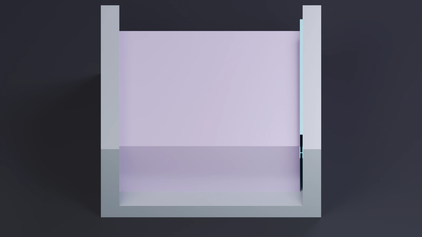
Nominal gap / Nominal sizes
20.00 − 19.70 = +0.30 mm
The intended sizes leave a 0.30 mm gap.
Check the fit in your assembly.
Import STEP geometry, set tolerances and inspect the gaps that matter.
What’s your assembly’s
fit question?
Bring one assembly and a decision that matters. We’ll help define a hands-on evaluation around it.